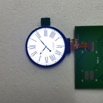


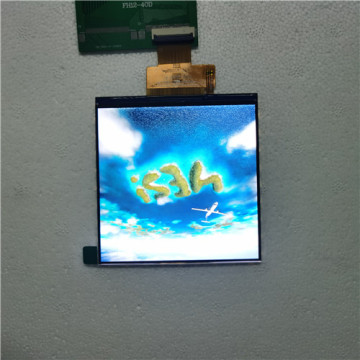
1.3 Inch LCD Display
- Payment Type:
- T/T
Your message must be between 20 to 2000 characters
Contact Now| Payment Type: | T/T |
|---|
A liquid crystal display or LCD draws its definition from its name itself. It is a combination of two states of matter, the solid and the liquid. LCD uses a liquid crystal to produce a visible image. Liquid crystal displays are super-thin technology display screens that are generally used in laptop computer screens, TVs, cell phones, and portable video games. LCD’s technologies allow displays to be much thinner when compared to a cathode ray tube (CRT) technology.
Liquid crystal display is composed of several layers which include two polarized panel filters and electrodes. LCD technology is used for displaying the image in a notebook or some other electronic devices like mini computers. Light is projected from a lens on a layer of liquid crystal. This combination of colored light with the grayscale image of the crystal (formed as electric current flows through the crystal) forms the colored image. This image is then displayed on the screen.
Model: 130003S0
Resolution: 240*240
Viewing angle: IPS
Color: 65K
Features: high brightness, full viewing angle, ultra-thin design with integrated backlight, low power consumption, square structure, etc.
Application: smart wear, children's toys, cameras/smart speakers, medical equipment, digital electronics, etc.


|
ITEM |
Sandard value |
Unit |
|
Model Number |
130003S0 |
|
|
size |
1.3 |
Inch |
|
LCD Type |
Normally black |
-- |
|
Drive element |
TFT active matrix |
-- |
|
Number of pixels |
240*3RGB(H)X240(V) |
Dots |
|
Pixel arrangement |
RGB stripe |
-- |
|
Pixel Pitch (W*H) |
0.153(H) *0.153 (V) |
mm |
|
Active area |
23.4(H) * 23.4(V) |
mm |
|
LCM Mechanical Outline Size(W*H*T) |
26.2 *29.15 *1.9 |
mm |
|
Viewing direction |
ALL O’CLOCK |
- |
|
LCM Driver IC |
ST7789V |
- |
|
LCM interface |
MCU 8 Bit Interface |
- |
|
Lcm pin n count |
24 |
|
|
Backlight leds |
2 |
pcs |
|
Backlight current |
40 |
ma |
|
Backligh voltage |
3.2 |
v |
|
-20+70 |
℃ |
|
|
storage temperature |
-30+80 |
℃ |
|
Lumens degrees |
400 |
Cd/㎡ |
1. Introduction
1.1 Scope of application
This specification applies to the LCD module that is supplied by
TIAN XIAN WEI TECHNOLOGY CO., LTD.
LCD specification: Dots 240xRGBx240
As to basic specification of the driver IC, refer to the IC (Sitronix:ST7789V)
specification and data book.
All material & processing of the LCD module should be Lead Free.
1.2 TFT features:
Structure: TFT PANNEL+IC +FPC+BL;
IPS Type LCD
240 dot-segment and 240 dot-common outputs;
262K Color can be selected by software;
White LED back light;
MCU 8 bit interface
1.3 Applications:
Pos
Pda
Electronic cigarettes
Law enforcement equipment,
walkie-talkie,
household appliances
2. LCM General specification
|
ITEM |
Sandard value |
Unit |
|
LCD Type |
Normally black |
-- |
|
Drive element |
TFT active matrix |
-- |
|
Number of pixels |
240*3RGB(H)X240 (V) |
Dots |
|
Pixel arrangement |
RGB stripe |
-- |
|
Pixel Pitch (W*H) |
0.0975(H) x0.0975 (V) |
mm |
|
Active area |
23.4(W) x23.4(H) |
mm |
|
Module Size(W*H*T) |
26.16(W) x29.22(H) x1.9(D) |
- |
|
Viewing direction |
ALL O’CLOCK |
|
|
TFT Driver IC |
ST7789V |
- |
|
TFT interface |
MUC 8 BITInterface |
- |
|
Approx. Weight |
TBD |
g |
|
Touch structure |
|
|
|
Touch Driver IC |
|
- |
|
Touch Interface |
|
|
3.Absolute Maximum Rating
|
Characteristics |
Symbol |
Min. |
Max. |
Unit |
|
LCM Operating Temperature |
TOPR |
-20 |
+70 |
°C |
|
LCM Storage Temperature |
TSTG |
-30 |
+80 |
°C |
|
TP Operating Temperature & Humidity(20% ~ 90%RH) |
TOPR |
|
|
°C |
|
TP SStorage Temperature & Humidity(20% ~ 90%RH) |
TSTG |
|
|
°C |
|
Humidity |
RH |
- |
90 |
% |
4.Electrical Characteristics
4.1 TFT DC Characteristics
|
Characteristics |
Symbol |
Min. |
Typ. |
Max. |
Unit |
|
Supply Voltage for I/O |
VDDIO |
1.65 |
1.8 |
3.3 |
V |
|
Supply Voltage for(DC/DC) |
VDD |
2.7 |
2.8 |
3.3 |
V |
|
Supply Voltage for(DC/DC) |
AVDD |
|
|
|
V |
|
Supply Voltage for(DC/DC) |
AVEE |
|
|
|
V |
|
Current Consumption |
IDD |
- |
TBD |
- |
mA |
|
IDD-SLEEP |
|
TBD |
|
uA |
4.2Back-Light Unit Characeristics
The back-light system is an edge-lighting type with 2 white LEDs. The characteristics of the back-light are shown in the following tables.
|
Characteristics |
Symbol |
Min. |
Type |
Max. |
Unit |
Notes |
|
Forward Voltage |
VF |
2.9 |
- |
3.2 |
V |
- |
|
Forward current |
IF |
30 |
40 |
|
mA |
- |
|
Luminance(With LCD) |
Lv |
350 |
380 |
400 |
cd/m2 |
- |
|
LED life time |
N/A |
---- |
30,000 |
-- |
Hr |
Note 1 |
Note:
(1) The “LED life time” is defined as the module brightness decrease to 50% of original brightness at IL=20mA/LED. The LED life time could be decreased if operating IL is larger than 25mA/LED.
Backlight circuit diagram shown in below:
5. Module Function Description
5.1 LCM Pin Descriptions
|
1 |
LEDA |
BACKLIGHT + |
|
2 |
LEDK |
BACKLIGHT- |
|
3 |
GND |
GROUND |
|
4 |
VCI |
POWER SUPPLY(2.8V) |
|
5 |
IOVCC |
POWER SUPPLY(1.8V) |
|
6 |
IM1 |
IM1=’0’4-line 8bit serial I/F,SDA: in/out IM1=’1’80-8bit parallel I/F ,DB0-DB7 |
|
7 |
RESET |
Hardware reset |
|
8 |
CS |
Chip selection pin |
|
9 |
DCX/SCL |
-Display data/command selection pin in parallel interface. -This pin is used to be serial interface clock. -DCX=’1’: display data or parameter. -DCX=’0’: command data. -If not used, please fix this pin at VDDI or DGND. |
|
10 |
WR |
Write enable in MCU parallel interface. Display data/command selection pin in 4-line serial interface. Second Data lane in 2 data lane serial interface. -If not used, please fix this pin at VDDI or DGND. |
|
11 |
RD |
Read enable in 8080 MCU parallel interface. -If not used, please fix this pin at VDDI or DGND. |
|
12 |
SDA |
SPI interface input/output pin. |
|
13-20 |
DB0-DB7 |
Data bus. |
|
21 |
TE |
Tearing effect signal is used to synchronize MCU to frame memory |
|
22 |
NC |
NC |
|
23 |
GND |
GROUND |
|
24 |
GND |
GROUND |
|
|
|
|
|
|
|
|
|
|
|
|
6. Timing Characteristics
6.1 80-system Bus Interface Timing Characteristics of IC
Table 8: Normal Write Mode (VCC = IOVCC=2.4~3.3V)
Figure 7. 4-line Serial interface Bus Timing
6.2 Reset Operation of IC
Table 9: Reset Timing Characteristics (VCC = IOVCC=2.4~3.3V)
Figure 8: Reset Timing
7.Optical Characteristics
Note 1: Definition of Contrast Ratio (CR):
The contrast ratio can be calculated by the following expression.
Contrast Ratio (CR) = L63 / L0
L63: Luminance of gray level 63
L0: Luminance of gray level 0
CR = CR (10)
CR (X) is corresponding to the Contrast Ratio of the point X at Figure in Note 5.
Note 2: Definition of Response Time (TR, TF):
Note 3: Viewing Angle
The above “Viewing Angle” is the measuring position with Largest Contrast Ratio; not for good
image quality. View Direction for good image quality is 6 O’clock. Module maker can increase
the “Viewing Angle” by applying Wide View Film.
Note 4: Measurement Set-Up:
The LCD module should be stabilized at a given temperature for 20 minutes to avoid abrupt
temperature change during measuring. In order to stabilize the luminance, the measurement
should be executed after lighting Backlight for 20 minutes in a windless room.
8. Reliability Test Item
|
No. |
Test Item |
Test Condition |
Notes |
|
1 |
High Temp. Storage |
+80°C / 120H |
1. Functional test isOK. Missing Segment,short, unclear segment non-display,display abnormally and liquid crystal leakare un-allowed. 2. No low temperature bubbles,end seal loose andfall, frame rainbow.
1. Function test is OK. 2. No glass crack,chipped glass, endseal loose and fall, epoxy frame crackand so on. 3. No structure loose and fall |
|
2 |
Low Temp. Storage |
-30°C / 120H |
|
|
3 |
High Tempe. Operating |
+70°C / 120H |
|
|
4 |
Low Tempe. Operating |
-20°C / 120H |
|
|
5 |
High Temperature /Humidity storage |
50+5°C x 90%RH / 48H |
|
|
6 |
Thermal and cold shock |
Static state, -30℃(1 hour) ~80℃ (1 hour) ~ -30℃(1 hour),packaging, 10 cycles |
|
|
7 |
Vibration Test |
Frequency: 10Hz~55Hz Amplitude:1.0mm, 2 hours for each direction of X, Y |
|
|
8 |
Dropping test |
Pack products into the carton box.Drop it from 80cm height to ground.Once for each side of the carton |
9. Packing Method----TBD
- END -

Related Keywords
-

4.0 Inch TFT LCD Module

3.5 Inch Color TFT LCD Display Screen

3.5 Inch Color LCD Display Screens
Related ProductsProduct Categories-
TFT LCD(99)
- 0.96-2.0 Inch TFT LCD(2)
- 2.2 Inch TFT LCD(1)
- 0.96 Inch TFT LCD(1)
- 1.3 Inch TFT LCD(4)
- 1.14 Inch TFT LCD(1)
- 1.54 Inch TFT LCD(6)
- 1.77 Inch TFT LCD(2)
- 2.0 Inch TFT LCD(7)
- 2.1 Inch TFT LCD(2)
- 2.4 Inch TFT LCD(10)
- 2.6 Inch TFT LCD(1)
- 2.7 Inch TFT LCD(2)
- 2.8 Inch TFT LCD(8)
- 2.31 Inch TFT LCD(3)
- 3.0 Inch TFT LCD(8)
- 3.2 Inch TFT LCD(4)
- 3.5 Inch TFT LCD(12)
- 4.0 Inch TFT LCD(3)
- 4.3 Inch TFT LCD(2)
- 4.5 Inch TFT LCD(2)
- 4.7 Inch TFT LCD(2)
- 5.0 Inch TFT LCD(3)
- 5.5 Inch TFT LCD(2)
- 6.0 Inch TFT LCD(2)
- 6.86 Inch TFT LCD(1)
- 7.84 Inch TFT LCD(1)
- 7.0 Inch TFT LCD(2)
- 8.0 Inch TFT LCD(1)
- 9.35 Inch TFT LCD(1)
- 10.1 Inch TFT LCD(2)
- 10.4 Inch TFT LCD(1)
-
Portable Air Conditioner(1)