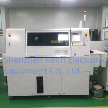

Panasonic Axial Lead Component Insertion Machine AV131
- Payment Type:
- T/T
- Incoterm:
- FOB, CIF, EXW
- Min. Order:
- 1 Bag/Bags
- Min. Order:
- 1 Bag/Bags
- Delivery Time:
- 7 Days
- Transportation:
- Ocean
- Port:
- Hong Kong
Your message must be between 20 to 2000 characters
Contact Now| Place of Origin: | Japan |
|---|---|
| Payment Type: | T/T |
| Incoterm: | FOB,CIF,EXW |
| Transportation: | Ocean |
| Port: | Hong Kong |
The AV131 is a VCD axial lead component insertion machine capable of high-speed insertion at a tact timeof 0.12 s/component, providing high economic efficiency.With the adoption of vertical feeders that allows multiple inputs (120 inputs) and the two separate supply units that improve operation rate, the AV131 is promising for greatly contributing to continuous unmanned operation.Also, the optionally available jumper wire insertion function enables insertion of jumper wires without the need for taping, which not only eliminates waste but also realizes highly efficient and flexible production.
Features
Higher Productivity
Insertion Tact Time
High-speed insertion at 0.12 s/component improves the productivity significantly.
High-speed X-Y Table
Lightweight and highly rigid design provides
higher speed X-Y table.
Insertion Tact Time for Four Directions
(0, 90, 180 and 270 degrees)
Compact and lightweight insertion unit and the direct drive
system adopting a hollow shaft motor offer high-speed
insertion while the insertion unit is rotating.
Two Separate Part Supply Units (NM-EJA3A)
Part supply unit separated into two tables allows the supply operation mode to be selected according to
the production needs, thus improving operation rate. (5 modes are available.)
Random-Access System
The random-access system allows insertion errors to be recovered quickly by just operating the buttons.
Higher Reliability
Longer Life Consumable Parts
Reversible tape cutter and
reversible lead cutter (fixed side)
offer a longer life of these
consumable parts.
The insertion guide and pusher
made from carbide materials also
ensure a longer life of them.
Circular Arc Flat Cable
The head and the anvil rotation unit adopting the circular arc flat cable offer a longer life for the wiring in
the movable section.
Centering Function
The centering function for correcting components off-centered on the tape prevents interference
between components and the insertion pusher, thus achieving highly reliable insertion.
Damper Type Tape Cutter Unit
The tape cutters provided with a damper of 2.5 mm stroke (5 mm in all) reduce possible damage to the
cutters in case foreign matter is caught in them.
Whole Area Self-correction Function as Standard Feature
Recognizes both of two holes at the insertion position to make optimum positional correction for stable
insertion.
In addition, corrections of rotational error and insertion pitch are also enabled for highly accurate
positioning (XY, θ and W), offering higher insertion rate.
| Power supply |
• Rated voltage 3-phase 200 / 220 / 380 / 400 / 420 / 480 V selectable • Frequency 50 / 60Hz • Rated capacity Approx. 4kVA |
||
| Air supply |
• Service air pressure 0.5 MPa • Air consumption Approx. 150 L/min. (A.N.R) Note: Quick coupler attached (SMC KK13P-03M, KK13S-03F). |
||
| Dimensions |
• NM-EJA3A W4070 × D1910 × H1610 mm (Not including signal tower) • NM-EJA2A W2810 × D1910 × H1610 mm (Not including signal tower) |
||
| Mass |
• NM-EJA3A Approx. 2,520 kg (main body only) • NM-EJA2A Approx. 1,750 kg (main body only) |
||
| Environmental requirements |
• Ambient temperature 20°C ± 10°C • Humidity 25 ~ 75%RH (with no condensation) • Height above sea level 1,000 m or below |
||
| Transport and storage |
• Ambient temperature -20 ~ 60°C • Humidity 75%RH or less (with no condensation) |
||
| Operating controls |
• Interactive operation via color LCD touch screen (Front and Rear: Standard equipment) English/Japanese/Chinese selectable with a single button Recognition screen (displays the recognized board image on a superimposed window) Hierarchical menu (Operator/Engineer) • I /O functions 3.5-inch FDD and SDD (standard equipment) • Communication RS-232C |
||
| Coating color | • Standard color White: W-13 (G50) | ||
| Insertion tact time |
• Max. tact time: 0.12 s/point Max. tact time conditions by component type and insertion direction |
||
|
Applicable component Insertion direction |
Axial lead component |
Jumper wire | |
| X (0°) | 0.15 s/point | 0.12 s/point | |
| Y (90°) | 0.12 s/point | 0.15 s/point | |
| -X (180°) | 0.15 s/point | - | |
| -Y (270°) | 0.24 s/point | - | |
|
Other conditions for max. tact time (0.12 s/point) • X-Y table movement Within 35 mm for X and 39.5 mm for Y (When interlock 2 is selected) (However, within 30 mm for X and 34 mm for Y when there are components above 3 mm high on the PCB. (When interlock 1 is selected)) • Feeder movement None (When the feeder moves by 1 pitch, the tact time will be 0.14 s/point.) |
|||
| Pitch changeover | • 5.3 mm within the tact time (0.12 s/point) | ||
| Applicable components |
• Taped axial lead components (carbon resistor, cylindrical ceramic capacitor, solid resistor, diode and taped jumper wire) • Jumper wire (optional) Refer to `Insertion Component Specifications` in this section for component dimensions. |
||
| Component packaging | • Flat pack | ||
| PCB replacement time | • Approx. 2 s (Ambient temperature: 20°C) | ||
| Applicable PCB |
• Dimensions Min. 50 × 50 mm to Max. 508 × 381 mm Width-to-length ratio: Width should be equal to or less than length. Consult us for boards having width longer than length. • Allowable insertion area Min. 50 × 40 mm to Max. 508 × 371 mm • Thickness 1.6 ± 0.15 mm (for standard specification) *1 Although boards of thicknesses from 0.6 mm (min.) to 2.0 mm (max.) are applicable, changes to the transfer rail (option) are required if outside the above standard range. *2 Even if the board thickness is within the above range, clinched angle of the inserted lead or lead length may vary, or board transfer error may occur depending on the shapes of board or insertion holes. So it is recommended to perform an advance evaluation. • Mass Max. 1 kg per board including inserted components. • Flow direction Right to left (Standard) or Left to right (option) • Board positioning method Pin positioning (Standard, without positioning in the Y direction), Edge positioning (Option, with positioning in the Y direction) * Contact us for the board positioning in the Y direction. |
||
| Insertion pitch |
• 5 ~ 26 mm (can be set in 0.01 mm increments) (Jumper wire: 5 to 26 mm (Option)) |
||
| Insertion direction | • 4 directions (X, Y, -X and -Y) | ||
| Anvil | • Cutting & Clinch type system (Piezoelectric detection system | ||
| No. of component inputs |
NM-EJA3A 1. Taping width: 26 mm 120 inputs (60 + 60) + drum type jumper wire (Option) 2. Taping width 52mm (Pack width Max. 80) 120 inputs (60 + 60) + drum type jumper wire (Option) 3. Mixed loading of 26 mm and 52 mm tapes is available. NM-EJA2A 1. Taping width 26 mm 60 inputs + drum type jumper wire (Option) 2. Taping width 52 mm (Pack width Max. 80) 60 inputs + drum type jumper wire (Option) 3. Mixed loading of 26 mm and 52 mm tapes is available. |
||
| Insertion height |
• Insertion height programmable according to the component diameter and lead diameter. |
||
| Clinching angle | • 15°to 30° inner clinching | ||
| Clinching length |
• 1.5 ± 0.3 mm (Reference size: 1.5 mm)*
differences in the diameter or material of inserted component leads and in the diameter of holes of PCBs. *When changing the clinching length (changing reference size), the anvil unit parts need to be replaced. (Individually supported) =REMARKS= 1. A clinch mark will be left after cutting or clinching. The shape of clinch mark varies with the lead diameter or material of the inserted component. 2. Clinched component will be tilted a maximum of ±10° in the horizontal direction due to the hole diameter of PCB or accuracy of hole position.
|
||


Shenzhen Keith Electronic Equipment Co., Ltd." located in Baoan District, Shenzhen. It is a supplier of AI and SMT equipment, spare parts, consumables and auxiliary consumption materials in China. Over the years, we have provided advanced equipment and parts for our customers to ensure high-quality service. And for exporting market, we are planing to developing Europe, North America, South America, Southeast Asia,India and where need SMT equipment spare parts.
Business philosophy: cooperation, win-win, innovation, mutual assistance
We have been adhering to the brand management concept of "focusing on product quality and customer needs", through the implementation of open innovation, excellent operation management, human resources development and other strategies, to comprehensively construct the core competitiveness of the company, create customer and social values, and win the unanimous praise of the vast number of customers and society.
Main products:
Panasonic Insertion Machine, Panasonic Insertion Machine Parts, Panasonic Placement Machine, Panasonic Placement Machine Parts, Panasonic Feeder & Feeder Parts, Feeder Trolley, SMT Cutter etc. To learn more about our products, please contact us through the following email address, look forward to your cooperation!

Related Keywords