


6.6kV MV Medium Voltage AC Drives
- Payment Type:
- L/C, T/T, D/P, Paypal, Western Union
- Incoterm:
- FOB, CFR, CIF, EXW
- Min. Order:
- 1 Set/Sets
- Min. Order:
- 1 Set/Sets
- Delivery Time:
- 30 Days
- Transportation:
- Ocean, Air
- Port:
- Shenzhen, Qingdao, Shanghai
Your message must be between 20 to 2000 characters
Contact Now| Place of Origin: | China |
|---|---|
| Productivity: | 1500 SETS/ YEAR |
| Supply Ability: | 2000 SETS/ YEAR |
| Payment Type: | L/C,T/T,D/P,Paypal,Western Union |
| Incoterm: | FOB,CFR,CIF,EXW |
| Certificate: | CE,ISO 9001, ISO 14001, OHSAS 18001 |
| HS Code: | 9032899090 |
| Transportation: | Ocean,Air |
| Port: | Shenzhen,Qingdao,Shanghai |
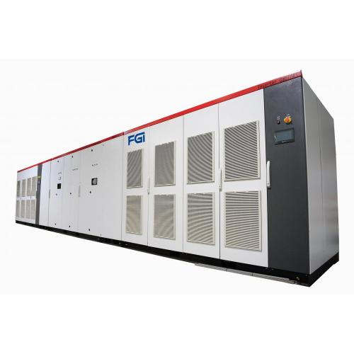
In operation, the upper part of the front of the inverter power cabinet is actually sucked by the hot air that has just been discharged for cooling, and the short-circuit wind that forms the airflow cannot achieve an effective cooling effect. The FGI 6600V series mv medium voltage IGBT driver sets the standard for reliability. The medium voltage drive draws on 20 years of experience with a wide range of industry applications and medium voltage training – including various pumps, different types of fans, and many compressors – to deliver the most reliable medium voltage vfd cable frequency drives available today. With high input power factor and good output waveform quality, the MV inverter has been widely used in harsh industrial fields including hoist, counter-rotating fan, axial fan, descaling pump and so on.
Structure

HMI: Provide users with friendly all-round document operation interface, responsible for dealing with information.
Power cabinet
Each phase is connected in series by a multi-level unit;
Unit standardized structure, 3kV/6kV/10kV unit junction is the same;
The unit communicates with the control cabinet through the optical fiber to control good performance.
Control cabinet
The control core is based on DSP+FPGA, the system is powerful and can meet the customer's needs to the greatest extent;
Independent main control box, plug-in control board, easy to install and maintain;
Rich interface with multiple choices.
Operating Principle

The medium voltage drive is composed of switch cabinet, phase shift transformer cabinet, power unit cabinet control cabinet. Among them, the switch cabinet is different according to different sites.The equipment adopts the high-high voltage source type inverter circuit structure, the power units are connected in series, the output is superimposed into high voltage, and directly output to the high voltage motor.

3kV series MV Drives with 3 units per phase / 6kV series MV Drives with 5 units per phase / 10kV series MV Drives with 8 units per phase

The power unit of the two-quad high voltage drive is mainly composed of rectifier diode, filter capacitor and IGBT. Each power unit is an H-bridge structure that outputs a set of SPWM waves.

The whole machine has several units per phase. Through the carrier phase shifting technology, the output voltages of each unit are superimposed to form a multi-level high voltage output. There is no need to output the filtering device, the current harmonics are small, and there is no damage to the cable and motor insulation. The figure shows output voltage waveform of each of the five units and the superposed voltage waveform.

When the motor is in the drag state, the energy flows from the rid through the rectification loop and the inverter loop to the motor, and the VFD works in the first and third quadrants. The input voltage and current waveforms are as shown.

The four-quad high voltage drive can perform energy feedback, and the power unit replaces the input rectifier diode with the IGBT with respect to the two-quad high voltage drives, realizing the energy bidirectional flow.

When the motor is in the power generation state, the DC bus voltage is greater than the input voltage, and the feedback control part inverts the DC voltage into an AC voltage, and the energy is fed back to the grid by controlling the voltage phase and amplitude. At this time, the energy flows from the motor to the grid through the inverter side and the feedback side. The inverter works in the second and fourth quadrants, and the feedback current and grid voltage waveform are as shown.
Performance Characteristics
Vector control technology
Multi master-slave control technology
Star drift technology
Output voltage automatic voltage regulation technology
Hot reset function
Frequency conversion without disturbance switching technology
Other Performance Characteristics
Flying start technology
Instantaneous power outage, drop without stopping (low voltage ride through)
Color full Chinese human machine interface
Dual loop control power supply
Multiple control methods
High power density ahead of the industry
Perfect protection mechanism
DC braking technology
Current limiting technology
Temperature pre-alarm technology
Overvoltage stall technology
High and low voltage ride through technology
Product Model Description and Dimensions


Specification
Product Model: JD-BP36-XXXXF / JD-BP36S-XXXXF / JD-BP37-XXXXF / JD-BP37S-XXXXF / JD-BP38-XXXXF / JD-BP38S-XXXXF
Power Level(kW): 200~20000kW (take 4-pole motor as standard, 6 to 12 pole motors are selected by current)
Output Voltage(kV): Three phase 0 ~ 3kV / Three phase 0 ~ 3.3kV / Three phase 0 ~ 6kV / Three phase 0 ~ 6.6kV / Three phase 0 ~ 10kV / Three phase 0 ~ 11kV
Rated Power(kW): Rated power of rated motor voltage: 200 ~ 20000kW
Rated Current(A): Rated current of rated motor voltage
Overload Capability: 105% continuous, 130% allowed 1min, 150% allowed 3s, 180% immediate protection
Waveform: Multiplexed SPWM sine wave
Frequency: 50Hz
Input Voltage: 3kV / 3.3kV / 6kV / 6.6kV / 10kV / 11kV
Allowable Range of Fluctuation: Voltage: -10%~+10%, -10%~-35% Derating continuous operation: frequency ±5%
Control Power Input: AC 220V 2kVA
Precision: Analog setting: 0.3% (25 ± 10 °C) below the maximum frequency setting. Digital setting: 0.02% (-10 ~ +50 °C) below the maximum frequency setting
Resolution: Analog setting: one thousandth of the highest frequency setting. Digital setting: 0.01Hz
Efficiency: >97%,when rated output
Power Factor: >0.95
High Voltage Isolation: Electromagnetic coupling, multi-channel fiber transmission
Acceleration, Deceleration Time: 0.1 to 6000.0s, for acceleration, deceleration time can be set separately
Voltage/Frequency Characteristics: 0: normal, 1: square curve, 2: multi-section V/F curve
Built-in PID: Easy to implement process closed-loop control
Operation Guide: The control (touch screen) operation, remote external control operation, upper computer operation (optional)
Frequency Given: Touch screen digital reference, multi-speed speed reference, external control analog signal (DC 4 ~ 20mA) given
Operating Status Output: Relay status output, inverter fault, alarm, run/stop status indication
Touch Screen Display: Input/output voltage, input/output current, set frequency, fault status of each unit, operating status, transformer status, bus voltage of each unit, etc.
Protective function: Motor over current, whole machine over voltage, whole machine under voltage, unit over current, unit over voltage, unit overheat, unit input phase loss, fiber communication failure, etc.
Digital Input: Total 15 channels
Digital Output: Total 15 channels
Analog Input: Three channels 4 ~ 20mA (channel can be set): frequency given, pressure feedback, motor temperature, etc.
Analog Output: Four channels 4 ~ 20mA (channel can be set): output frequency, output current, output voltage, excitation control (for synchronous motor control)
Communication Interface: One RS485 interface, support MODBUS and PROFIBUS protocol; one channel CAN interface
Place of Use: Indoor, no corrosive or conductive gas, dust, direct sunlight, altitude below 1000m (high altitude area can be customized)
Ambient Temperature / Humidity: -10°C~ +40°C /20% ~ 90%RH No condensation
Place of Use: 5.9m/ s2 (below 0.6g)
Storage Temperature: -20°C~ +65°C (for short-term storage such as transportation)
Cooling Method and Enclosure Protection Level: Forced air cooling / IP31
Selection Guide
Type of Inverter Power Level Size and Weight
(W) width(mm) (D)depth(mm) (H) height(mm) weight(kg)
JD-BP37S-250F 250kW/6kW 2300 1500 1900 1320
JD-BP37S-250F 280kW/6kW 2300 1500 1900 1380
For more information, please see the following picture.

Application
Power generation
Boiler feed water pump, blower, induced draft fan, condensate pump, circulating water pump, mortar pump, compressor, vacuum fan, booster fan
Petroleum, petrochemical, natural gas fields
Air compressor, induced draft fan, pipeline pump injection pump, oil pump feed pump, submersible pump, circulating water pump, brine pump
Coal, mining field
Hoist, counter-rotating fan, axial fan, descaling pump, agitating pump, dust removing fan, mud pump, slurry pump, clean water pump, feed pump, drain pump, medium pump
Metallurgical field
Dust removal fan, blast furnace blower, induced draft fan, compression fan, oxygen compressor, blower, feed pump, water pump, descaling pump, SO2 fan, slag machine converter, electric furnace, blast furnace, descaling pump, gas compressor
Cement and building materials
Raw material grinding induced draft fan, cement grinding fan, sorter fan kiln induced draft fan, kiln supply fan, tail exhaust fan, high temperature fan coal mill, dust removal fan, circulation fan, pressure blower
Light industry, chemical industry
Pressurized pump, compressor, axial pump, soft water pump, blower, induced draft fan

Our Service
OEM Service is available
After-sales responding within 24 hours
One to one pre-sales consulting services
We are factory with high-tech professional engineer teams
Technician could be assigned to go abroad to carry out site commissioning and technical training


Related Keywords


