

2V Online Battery Smart Protector System
- Payment Type:
- L/C, T/T
- Incoterm:
- FOB
- Min. Order:
- 2500 Piece/Pieces
- Min. Order:
- 2500 Piece/Pieces
- Delivery Time:
- 35 Days
- Transportation:
- Ocean, Air
- Port:
- SHENZHEN
Your message must be between 20 to 2000 characters
Contact Now| Place of Origin: | SHENZHEN, CHINA |
|---|---|
| Productivity: | 3000PCS/Month |
| Supply Ability: | 36000PCS/Year |
| Payment Type: | L/C,T/T |
| Incoterm: | FOB |
| Certificate: | CE, REACH,ROHS,ISO |
| HS Code: | 8536300000 |
| Transportation: | Ocean,Air |
| Port: | SHENZHEN |
This 2V Online Battery Smart Protector System is only used for the maintenance of new batteries in Telecom Base site, or used after repaired by our off-line Battery Repair System. Prohibit the use of aged batteries in the absence of being repaired. Once the violation, it may not reach your expectations. It is designed as Battery Protector System plus Equalizer of new batteries in Telecom base sites. We also call it as well as Smart Battery Protective System for its:
- MCU ( Micro-controller Unit) design, Constantly scanning the battery terminal voltage and reasonable output digital intelligent resonance pulse.
- Built-in 8 bit precise A/D converting circuit to real-time monitor battery voltage, according to the change of cells terminal voltage value, smartly and automatically switch in 3 working states of under-voltage shutdown protection, cells equalized and optimized charging maintenance and pulse maintenance work
- The decrease of cells internal resistance, improve the cells capacity consistency of the series battery bank
- Without any damage on charging equipment and battery plates
- Has the function of over-current protection, even inadvertently reverse polarity will not damage their own instruments
- Also has voltage detection and equalization circuit, can significantly improve the equalization of cell voltage and capacity
- The long-term work in parallel at the battery, the sulfated crystals can be effectively removed, and prevent the new sulphation buildup. The battery capacity is significantly maintained as new one for long time.
Due to the rapid development of the Internet, the Internet of Things and communication technology, the number of telecom base site and it's stationary battery has increased rapidly. But in order to ensure the 4G/5G signal uninterrupted , each base station has a fixed backup battery to ensure the continuity of telecommunications services. A loss of backup power during an outage without Online Battery Smart Protector System and Monitoring System can cause not only lost business, but also costly repairs. However, replacing backup batteries based on a periodic schedule is inefficient and lots of the batteries may still have a lot of life left in them. This is huge waste of money and battery resources.
2V Telecom Base Site Smart Battery Protective System is working as a new generation of high-tech products for daily battery maintenance and battery equalization in sites or other stationary power system.
APPLICABLE SCOPE:
It is used for 6V/200AH-6V1000AH battery bank series by 3 PCS 2V/200AH-2V/1000AH Lead Acid Cells.
IMPORTANT CLAUSE:
It is only used for the Maintenance and Life extension of new batteries in Telecom Base site, or used after repaired by our off-line Battery Repair System.
Prohibit the use of aged batteries in the absence of being repaired. Once the violation, it may not reach your expectations.
ENVIRONMENT CONDITIONS:
- The ambient temperature: -10℃~50℃
- The storage temperature: -40℃~70℃
- The relative humidity of the environment: 45%~90%
- The atmospheric pressure: 86-106mpa
ELECTRICAL PARAMETERS (Pulse Maintenance Status)
- The maximum current:≤280mA
- The maximum power consumption:≤1,97w
- The pulse frequency: 8,4kHz±20%
- The working voltage range: 6,00V±0,1V~7,05V±0,1V
- The pulse peak current:≥1,0A(no sense of sampling resistance test)
- The maximum pressure: 16V
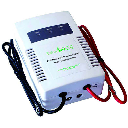
PRODUCT STRUCTURE AND INSTALLATION MAP

Fig. 1: Structure and Function Description
① Equipment shell.
② Negative pole of input / output line.
③ Positive pole of input / output line.
④ Trigger signal output line.
⑤ Trigger signal input line.
⑥ Trigger signal output jack.
⑦ Trigger signal input jack.
⑧ Trigger signal: the signal flashes once, indicating that the maintenance system stops working, enters the waiting state and sends out a signal to trigger the next maintenance system equipment to enter the working state.
⑨ Status indicator: display maintenance system working status. The indicator light is green to work in pulse maintenance state; red denotes working undervoltage state; flashing red denotes working in over-voltage equilibrium state; extinction indicates waiting state.
⑩ Power indicator.
⑪ Start button.
⑫ Reset button.
WARRANTY: 2 Years

Fig. 2: Installation Structure Map Description
WARRANTY:2 Years


Related Keywords


