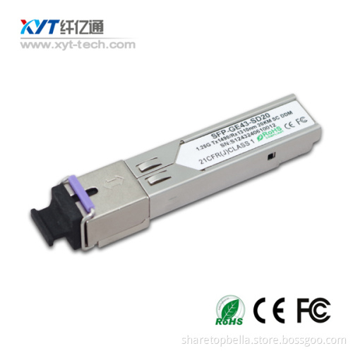
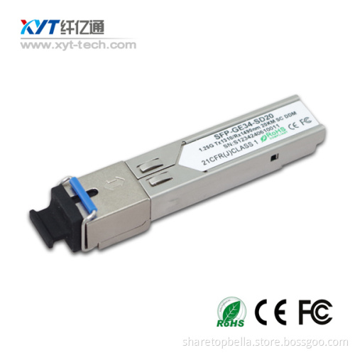

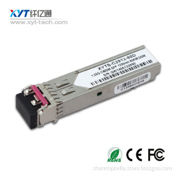
SFP 1.25G 1531.12nm 120km optical transceiver
Your message must be between 20 to 2000 characters
Contact NowDescription
The SFP transceivers are high performance, cost effective modules supporting multi-rate of 155Mbps~1.25Gbps and 120km transmission distance with SMF. The transceiver consists of three sections: a FP laser transmitter, a PIN photodiode integrated with a trans-impedance preamplifier (TIA) and MCU control unit. All modules satisfy class I laser safety requirements. The transceivers are compatible with SFP Multi-Source Agreement (MSA) and SFF-8472. For further information, please refer to SFP MSA.
Features
1.Operating data rate up to 1.25Gbps
2.TX1531 FP laser and PIN photodetector for 120 km transmission with SMF
3.PIN photodetector for 100m transmission with SMF
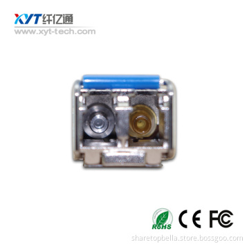
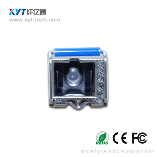
4.Meet SFP MSA and SFF-8472 with LC receptacle
5.Metal Enclosure for Lower EMI
6.Comply with SFP MSA
7.Operation Temperature Range 0~70oC or -40~85oC Optional
8.Single +3.3V Power Supply
9.RoHS-6 Compliant
Applications
1.Gigabit Ethernet
2.Fiber Channel
3.WDM Application
4.Switch to Switch interface
5.Switch backplane applications
6.ATM
7.SONT/SDH/PDH
8.FDDI
9.Other optical transmission syste
Table 1 - Optical and Electrical Characteristics
|
Parameter |
Symbol |
Min |
Typical |
Max |
Unit |
Notes |
||
|
Transmitter |
||||||||
|
Centre Wavelength |
λc |
1260 |
1310 |
1360 |
nm |
|
||
|
Spectral Width (RMS) |
∆λ |
|
|
4 |
nm |
|
||
|
Average Output Power |
Pout |
-9 |
|
-3 |
dBm |
1 |
||
|
Extinction Ratio |
ER |
9 |
|
|
dB |
|
||
|
Optical Rise/Fall Time (20%~80%) |
tr/tf |
|
|
0.26 |
ns |
|
||
|
Data Input Swing Differential |
VIN |
400 |
|
1800 |
mV |
2 |
||
|
Input Differential Impedance |
ZIN |
90 |
100 |
110 |
Ω |
|
||
|
TX Disable |
Disable |
|
2.0 |
|
Vcc |
V |
|
|
|
Enable |
|
0 |
|
0.8 |
V |
|
||
|
TX Fault |
Fault |
|
2.0 |
|
Vcc |
V |
|
|
|
Normal |
|
0 |
|
0.8 |
V |
|
||
|
Receiver |
||||||||
|
Centre Wavelength |
λc |
1260 |
|
1580 |
nm |
|
||
|
Receiver Sensitivity |
|
|
|
-23 |
dBm |
3 |
||
|
Receiver Overload |
|
-3 |
|
|
dBm |
3 |
||
|
LOS De-Assert |
LOSD |
|
|
-24 |
dBm |
|
||
|
LOS Assert |
LOSA |
-35 |
|
|
dBm |
|
||
|
LOS Hysteresis |
|
1 |
|
4 |
dB |
|
||
|
Data Output Swing Differential |
Vout |
400 |
|
1800 |
mV |
4 |
||
|
LOS |
High |
2.0 |
|
Vcc |
V |
|
||
|
Low |
|
|
0.8 |
V |
|
|||
Notes:
1. The optical power is launched into SMF.
2. PECL input, internally AC-coupled and terminated.
3. Measured with a PRBS 27-1 test pattern @1250Mbps, BER ≤1×10-12.
4. Internally AC-coupled.
Related Keywords