

Serial Port Bluetooth Module Master Arduino Compatible
- Payment Type:
- T/T, Western Union, Paypal, Money Gram
Quantity:
Your message must be between 20 to 2000 characters
Contact NowBasic Info
Basic Info
| Place of Origin: | China |
|---|---|
| Payment Type: | T/T, Western Union, Paypal, Money Gram |
Product Description
Product Description
Serial Port Bluetooth Module (Master)
Industrial serial port bluetooth, Drop-in replacement for wired serial connections, transparent usage. You can use it simply for a serial port replacement to establish connection between MCU and GPS, PC to your embedded project and etc.
Default serail port setting: 115200(optional 4800, 9600, 19200), N, 8, 1
Pairing code: 1234
Running in slave role: Pair with BT dongle and master module.
Specification:
Bluetooth protocal: Bluetooth Specification V2.0+EDR
Frequency: 2.4GHz ISM band
Modulation: GFSK(Gaussian Frequency Shift Keying)
Emission power: ≤ 4dBm, Class 2
Sensitivity: ≤ -84dBm at 0.1% BER
Speed: Asynchronous: 2.1Mbps(Max) / 160 kbps; Synchronous: 1Mbps/1Mbps
Security: Authentication and encryption
Profiles: Bluetooth serial port(master & slave)
CSR chip: Bluetooth V2.0
Wave band: 2.4GHz— 2.8GHz, ISM Band
Protocol: Bluetooth V2.0
Power Class: (+6dBm)
Reception sensitivity: -85dBm
Voltage: +3.3V 50mA (2.7V— 4.2V)
Current: Paring - 35mA, Connected - 8mA
Temperature: -20~ +55
User defined Baud rate:
200, 4800, 9600, 19200, 38400, 57600, 115200, 230400, 460800, 921600, 1382400
Dimension: 26.9mm*13mm*2.2mm
Coupled Mode: Two modules will establish communication automatically when powered.
PC hosted mode: Pair the module with bluetooth dongle directly as virtual serial.
Pin Definition:
Common Pin Explanation:
1, PIO8 connects with LED cathodea with 470ohm series resistor in between. LED NEGATIVE connects to ground. It is used to indicate the module state. After powered on, flashing intervals differ in different states.
2, PIO9 is used to control LED indicating paring. It will be steady on when paring is successful.
3, PIO11, module state switching pin. HIGH -> response to AT command; LOW or floating -> regular work status.
4, With build-in reset circuit, reset is completed automatically after powered on.
Steps to set as master mode:
1, Set PIO11 HIGH with a 10K resistor in between.
2, Power on, module comes into AT Command Response Status
3, Open HyperTerminal or other serial tool, set the baud rate 38400, 8 data bits, 1 stop bit, no parity bit, no Flow Control
4, Via serial port, send characters "AT + ROLE = 1 r n", if successful, return "OK r n", where r n is carriage return.
10, Set PIO11 LOW, re-power, then in Master state, automatically search for slave module and connect.
Application:
Computer and peripheral devices
GPS receiver
Industrial control
MCU projects
Document Download Area:
Click to Download the datasheet
Click to Download the manual
Click to Download the AT Command
Related Keywords
Related Keywords
You May Also Like
You May Also Like
-

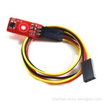
Reflectional Infrared Switch Sensor 2cm Arduino Compatible

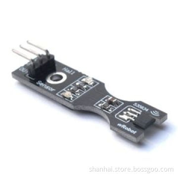
Wrobot Hall Velocity Measurement Sensor

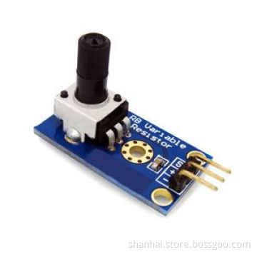
High Sensitivity Rotary Angle Sensor 1 Arduino Compatible
Related ProductsProduct Categories-
Antenna(1)
-
PCBA(30)
-
Optical Fiber(1)
-
Acceleration Sensor(2)
-
Gas Sensor(2)
-
Image Sensor(2)
-
Infrared Sensor(6)
-
Pressure Sensor(1)
-
Temperature & Humidity Sensor(3)
-
Ultrasonic Sensor(2)
-
Voltage Sensor(1)
-
Speaker,Trumpet & Buzzer(1)
-
Sensor Switch(1)
-
Membrane Switch(1)
-
GPS(6)
-
Communication Module(16)
-
Fixed Wireless Terminals(2)
-
Electronics Stocks(31)
-
Remote Control(1)
-
Sender, Receiver(1)
-
EAS & Accessories(1)
-
Other Car Accessories(1)
-
Car Radar(1)
-
Other Tires(1)


