
Arduinocyclic Rgbuino Shield V3 0 Arduino Compatible
- Payment Type:
- T/T, Western Union, Paypal, Money Gram, Paypal
Quantity:
Your message must be between 20 to 2000 characters
Contact NowBasic Info
Basic Info
| Place of Origin: | China |
|---|---|
| Payment Type: | T/T, Western Union, Paypal, Money Gram, Paypal |
Product Description
Product Description
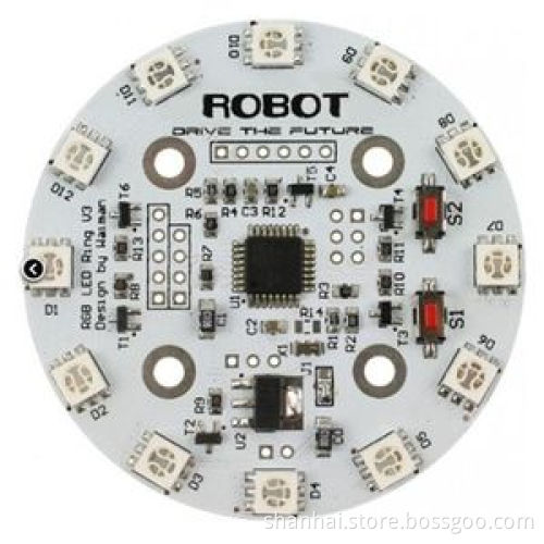
Cyclic RGBuino Shield has been upgraded to version 3.
This is probably the most beautiful LED ring ever. Each LED on the ring can be controlled seperatly on its brightness and colors (RGB). It comes with pre-burned bootloader which has several built in LED scripts.
It allows I2C/Serial communication from any MCU and can be serially linked to make a beautiful Art piece via I2C.
It can be programmed using standard Arduino IDE by FTDI breakout board.
Specificiation
1, CPU: Atmega 168P (Lilypad Board in Arduino IDE)
2, Bootloader: Optiboot diecimila
3, Supply voltage: 5V
4, Output voltage: 5V
5, Interface: Serial/I2C/Digital pins
6, Push button X2
7, 12 SMD RGB LED
8, Firmware upgradable
9, Stand-alone operation: No microcontroller needed for light script playback
Procedure
Cyclic RGBuino Shield ships with no pin headers. This gives you the option to solder the pins according to your project needs. Before starting to program the LED Ring you should solder the pin headers on to the board.
1) FTDI connection instructions
After soldering your pin headers, connect your Cyclic RGBuino Shield to the FTDI board as shown in the diagram
Caution: Only supply power to 1 of the 3 power pins provided at any one time.
Once you have connected the Cyclic RGBuino Shield to the FTDI breakout board connect the FTDI board to your PC. After windows has finished installing the drivers, find which COM port it was assigned to by going to Control Panel and then Device Manager.
2) I2C connection instructions
Note: Do not connect 5V if already connected from the FTDI board
Connect your Arduino to the Rainbow Ring. Since we are providing power from the FTDI board do not plug in the 5V Vcc to the I2C side of the Rainbow Ring. The only 3 wires you need to connect are the SDA to pin 4, SCL to pin 5, and GND.
Related Keywords
Related Keywords
You May Also Like
You May Also Like
-

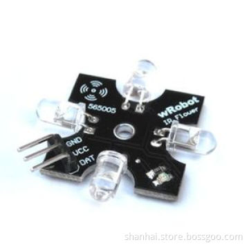
Wrobot 4 Directional Digital 38kHz IR Transmitter Sensor Arduino Compatible

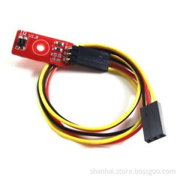
Reflectional Infrared Switch Sensor 2cm Arduino Compatible

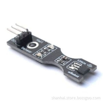
Wrobot Hall Velocity Measurement Sensor

High Sensitivity Rotary Angle Sensor 1 Arduino Compatible
Re200b Can 3 Human Body IR Pyroelectricity Sensor
Related ProductsProduct Categories-
Antenna(1)
-
PCBA(30)
-
Optical Fiber(1)
-
Acceleration Sensor(2)
-
Gas Sensor(2)
-
Image Sensor(2)
-
Infrared Sensor(6)
-
Pressure Sensor(1)
-
Temperature & Humidity Sensor(3)
-
Ultrasonic Sensor(2)
-
Voltage Sensor(1)
-
Speaker,Trumpet & Buzzer(1)
-
Sensor Switch(1)
-
Membrane Switch(1)
-
GPS(6)
-
Communication Module(16)
-
Fixed Wireless Terminals(2)
-
Electronics Stocks(31)
-
Remote Control(1)
-
Sender, Receiver(1)
-
EAS & Accessories(1)
-
Other Car Accessories(1)
-
Car Radar(1)
-
Other Tires(1)


