
Hitachi C5470YE Monitor Replacement/Repair (GBS8219)
- Payment Type:
- T/T, Western Union
Quantity:
Your message must be between 20 to 2000 characters
Contact NowBasic Info
Basic Info
| Place of Origin: | Shenzhen China |
|---|---|
| Payment Type: | T/T, Western Union |
Product Description
Product Description
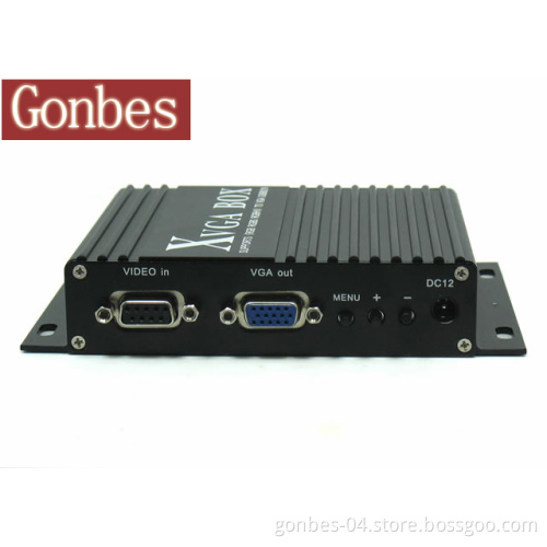
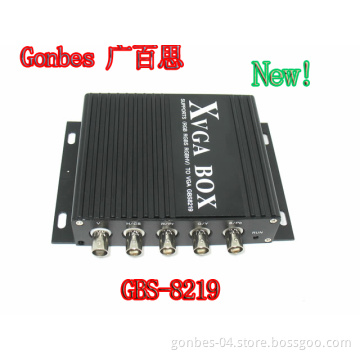
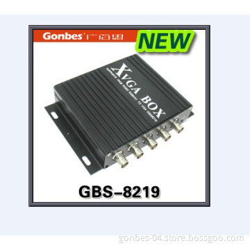
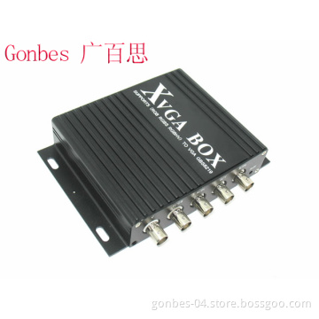
Model No: GBS-8219
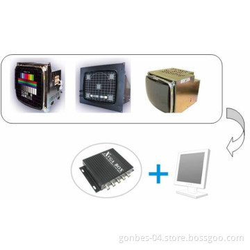
C-5470YE Hitachi Monitor
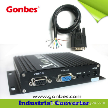
8219 CNC Monitor Converter uses the latest technology to replace your old or damage industrial CRT Monitor with a common minitor. It brings you very good images in a low price.
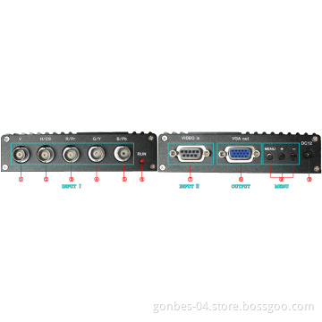
Input
Signals
MDA\CGA\EGA\RGB\RGB Sog\RGBS\RGBHV\YPbPr
Interface
5BNC, 9pin\3pin\6pin\14pin\20pin\25pin
Horizontal Frequency Rate(H)
12kHz to 40kHz automatically recognized
Output
Supports
D-15pin standard VGA/SVGA, Resolution: 800*600/60Hz, 640*480/60Hz
Interface
D-SUB 15 PIN standard VGA port
Power
DC 12V 1.0A
Note:
1. YPbPr = YUV
2. Input Horizontal Frequency Rate 12kHz to 40kHz automatically recognized.
3. Support RGB and YPbPr
4. Support Interlaced Scanning and Line by Line Scanning.
5. Support Vertical Resolution from line200 to line 600 automatically recognized.
6. Support variable Horizontal Resolution automatically recognized.
7. Support RGBHV (separate sync), RGBS (composite sync), automatically recognized
8. Output resolution: 800*600/60Hz standard VGA or custom-resolution.
MENU
Use to adjustscreen /programming
DC12
Power inputDC12V, 1A
Table 4.1 Definition for Input Channel II:
PIN InputSignal
P1(GND)
Connect to the ground
P2(GND)
Connect to the ground
P3(R)
Connect R(ED) interface of the input device
P4(G)
Connect G(reen) interface of the input device
P5(B)
Connect B(lue) interface of the input device
P6
Undefined(null)
P7
Undefined(null)
P8(H)
Connect H(CS) interface of the input device
P9(V)
Connect V interface of the input device
Figure 4.1 Definition for Input Channel II
Table 4.2 Definition for Input Channel I: BNC
Input Signal
Connection image
Pb\Y\Pr
YPbPr input signal (right image) Interface: Three BNC slot, connected to the corresponding Pb, Y, Pr interface, then Y monochrome port.
Figure 4.2 Analog 3BNC (YPbPr) Input.
R\G\B
RGB Sog input signal (right image) Interface: Three BNC slot, connected to the corresponding R, G, B slot, then G monochrome port.
Figure 4.3 Analog 3BNC (RGB Sog) Input.
R\G\B\S
RGBS CS Composite Sync (right image) Interfaces: 4 BNC slot, connected to the corresponding R, G, B, S I, monochrome then G, S I
Figure 4.4 Analog 4BNC (RGBS CS) Input.
R\G\B\H\V
RGBHV separate sync (right image) Interface: 5 BNC port, connected to the corresponding R, G, B, H, V I, monochrome then G, H, V I
Figure 4.5 Analog 5BNC (RGBHV) Input.
Operation Menu:
Item
Spec.
MENU
-press it to enter into OSD menu -click it once to select and click again to exit the current line
"+"
-click it to move the cursor up -click it to add the value
"-"
-click it to move the cursor down -click it to deduct the value
C-5470YE Hitachi Monitor
8219 CNC Monitor Converter uses the latest technology to replace your old or damage industrial CRT Monitor with a common minitor. It brings you very good images in a low price.
Input
Signals
MDA\CGA\EGA\RGB\RGB Sog\RGBS\RGBHV\YPbPr
Interface
5BNC, 9pin\3pin\6pin\14pin\20pin\25pin
Horizontal Frequency Rate(H)
12kHz to 40kHz automatically recognized
Output
Supports
D-15pin standard VGA/SVGA, Resolution: 800*600/60Hz, 640*480/60Hz
Interface
D-SUB 15 PIN standard VGA port
Power
DC 12V 1.0A
Note:
1. YPbPr = YUV
2. Input Horizontal Frequency Rate 12kHz to 40kHz automatically recognized.
3. Support RGB and YPbPr
4. Support Interlaced Scanning and Line by Line Scanning.
5. Support Vertical Resolution from line200 to line 600 automatically recognized.
6. Support variable Horizontal Resolution automatically recognized.
7. Support RGBHV (separate sync), RGBS (composite sync), automatically recognized
8. Output resolution: 800*600/60Hz standard VGA or custom-resolution.
MENU
Use to adjustscreen /programming
DC12
Power inputDC12V, 1A
Table 4.1 Definition for Input Channel II:
PIN InputSignal
P1(GND)
Connect to the ground
P2(GND)
Connect to the ground
P3(R)
Connect R(ED) interface of the input device
P4(G)
Connect G(reen) interface of the input device
P5(B)
Connect B(lue) interface of the input device
P6
Undefined(null)
P7
Undefined(null)
P8(H)
Connect H(CS) interface of the input device
P9(V)
Connect V interface of the input device
Figure 4.1 Definition for Input Channel II
Table 4.2 Definition for Input Channel I: BNC
Input Signal
Connection image
Pb\Y\Pr
YPbPr input signal (right image) Interface: Three BNC slot, connected to the corresponding Pb, Y, Pr interface, then Y monochrome port.
Figure 4.2 Analog 3BNC (YPbPr) Input.
R\G\B
RGB Sog input signal (right image) Interface: Three BNC slot, connected to the corresponding R, G, B slot, then G monochrome port.
Figure 4.3 Analog 3BNC (RGB Sog) Input.
R\G\B\S
RGBS CS Composite Sync (right image) Interfaces: 4 BNC slot, connected to the corresponding R, G, B, S I, monochrome then G, S I
Figure 4.4 Analog 4BNC (RGBS CS) Input.
R\G\B\H\V
RGBHV separate sync (right image) Interface: 5 BNC port, connected to the corresponding R, G, B, H, V I, monochrome then G, H, V I
Figure 4.5 Analog 5BNC (RGBHV) Input.
Operation Menu:
Item
Spec.
MENU
-press it to enter into OSD menu -click it once to select and click again to exit the current line
"+"
-click it to move the cursor up -click it to add the value
"-"
-click it to move the cursor down -click it to deduct the value

Related Keywords
Related Keywords
You May Also Like
You May Also Like
-

3D Active Shutter Glasses for TV

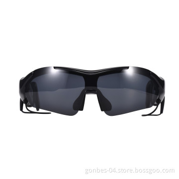
K1 Smart Multifunction Bluetooth Sunglasses MP3 Voice Navigation

Hitachi CD1472D1M2 CNC Monitor Replacement/Repair (GBS-8219)

Industrial CNC Monitor Replacement, Old CRT Monitor Replacement
2013 Universal Active Shutter 3D DLP Glasses for Benq DLP Projector
Related Products-
Hitachi CD1472D1M2 CNC Monitor Replacement/Repair (GBS-8219)
-
CNC Monitor Replacement Video Converter (GBSG8219)
-
CNC Industrial Monitor Replacement-Cga / Ega / RGB to VGA Converter (GBS-8219)
-
Hitachi Tx-1424ad Monitor Replacement/Repair (GBS-8219)
-
Fanuc A61L-0001-0092 Monitor Display Replacement (GBS-8219)
Product Categories-
Sunglasses(1)
-
Home Theatre System(1)
-
Audio & Video Products(2)
-
LCD Display(1)
-
Entertainment Electronics(28)
-
LCD TV(2)
-
Other TV & Parts(27)
-
Other Videos(5)
-
Video Glasses(1)
-
Coaxial Connector(4)
-
Terminals(5)
-
Electrical Control System(9)
-
Specialized Electrical Equipment(9)
-
Communication Module(2)
-
3D Glasses(31)
-
Manufacturing Equipment for Electrical & Electronic Product(15)
-
Intellectual & Educational Toys(1)
-
Monitor(1)
-
Sports Glasses(32)


